|
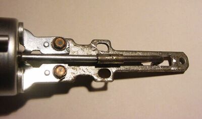
When boost increases beyond a certain point, the ignition timing must be retarded correspondingly to prevent detonation. This feature is especially critical with today's lower octane (compared to 1978) gasoline. The original TurboFORCE used a modified 1962 Corvair Turbo non-HEI vacuum advance & boost retard. The current setup uses exactly the same thing. But these units are getting hard to find and are expensive. A sophisticated electronic knock-sensor retard is the next step, but for now...
|
|
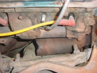
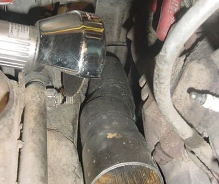
TurboFORCE mounts the turbocharger low on the passenger side and routes the turbine exhaust outlet pipe between the P-side exhaust manifold and crossmember. However, there's not quite enough room for the 2-1/2" pipe. This picture shows the clearance required.
|
|
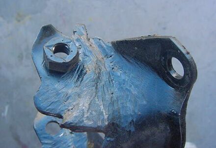
The Gen-2 Firebird motor mount on the engine is a stamped steel piece. The height must be increased by approximately 7/8" from stock. This is accomplished by cutting and welding a spacer in the stock motor mount, as shown.
|
|
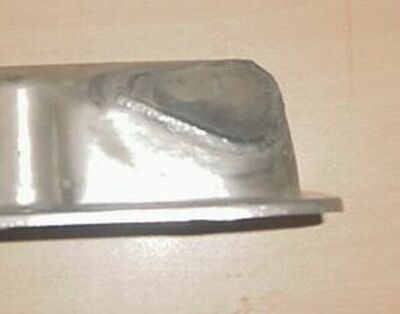
After the engine is raised on the passenger side, this creates an interference between the driver side valve cover (outer rear) and the vacuum booster. The valve cover is "clipped" (cut and welded) to make clearance as shown.
|
|
The downstream 2-1/2" exhaust pipe is still a close fit even with the P-side raised. Cutting off approximately 1/2-inch of the unused end of the rearmost upper control arm stud provides sufficient clearance.
|
|
A modified front timing cover is used with TurboFORCE. There are three modifications required. (1) The heater hose outlet is tilted slightly upward to clear the turbine, (2), the lower radiator inlet is repositioned pointing approximately forward (also to clear the turbine and miss the A/C drive belt) and (3) an oil drain hole (3/8 NPT) is drilled in a filled-in lower left corner. All are shown in this picture.
|
|
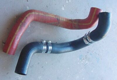
Because the lower radiator hose (inlet) is repositioned (see above), a different routing on the radiator hose is required. This picture shows the original silicone specially made hose with one I made up from two stock hoses and a hose mend kit. Not as elegant, but just as functional.
|
|
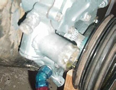
The turbo center section must drain oil back into the oil pan. This is how I routed it using Earl's Race Plumbing components. There is a less pretty, less expensive way to do it which is just as functional. This view is from underneath; compare it with the front cover picture above. The exhaust turbine inlet pipe (not yet attached) DOES clear everything by a good margin.
|
|
A turbo center section also requires an oil feed line (duh). I got the feed from the normally plugged oil gallery next to the distributor. One could also get it from the oil filter housing. Excuse the " 7-years parked in the Nevada desert" dirt and oil in this picture and elsewhere. I'll post a pretty one later.
|
|
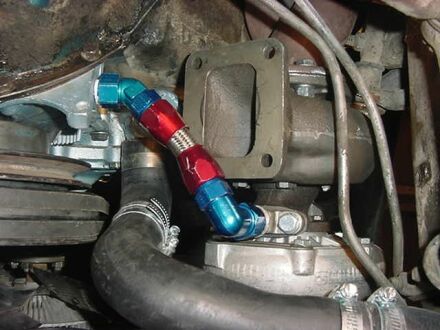
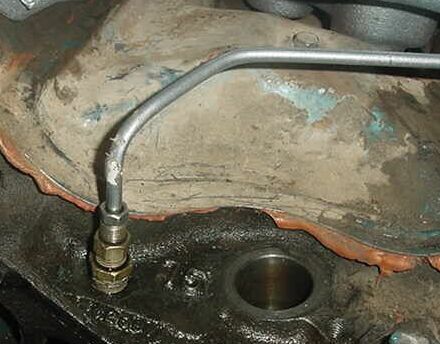
Here's the turbo-end of the oil feed line. The 1/4" steel line could be replaced by Earls steel braided or whatever. This particularly routing is sans A/C compressor. If so equipped, the routing would be somewhat different.
|
|
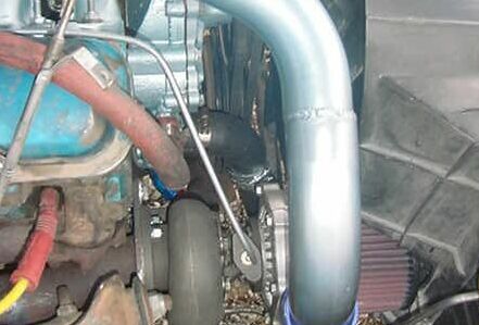
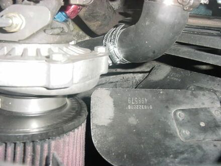
Seen in the above picture is the K&N air filter attached to turbo inlet. The fan shroud must be clipped for fit, as shown.
|
|
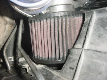
Here is an view of the K&N air filter from inside the shroud (a fan's eye view, so to speak) |
|
Speaking of the fan, here's how it (barely) clears the filter, turbo and lower radiator hose. Hey, an inch is a mile! And since they all are attached to the engine and move together, there's no problem.
|
|
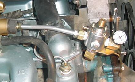
Last, but not least is the boost-referenced fuel pressure regulator. The back end of the fuel system is the same as any decent stock-type drag car: no mechanical pump, high pressure, big volume electric pump in the back, 1/2" pickup in the tank, 3/8" return line (to make the regulator work). The only difference here is that the regulator is boost-referenced (although the line to the bonnet is not connected in this shot). The regulator is set at 6psi above boost. This is the way I did it. You can " roll your own".
|